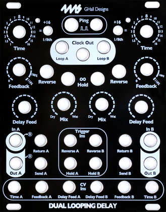
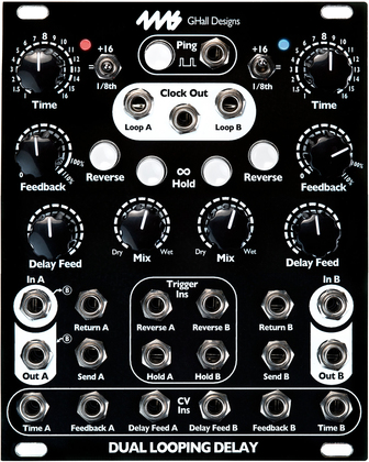
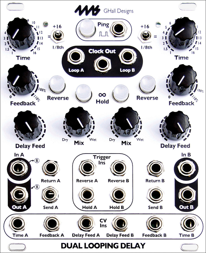
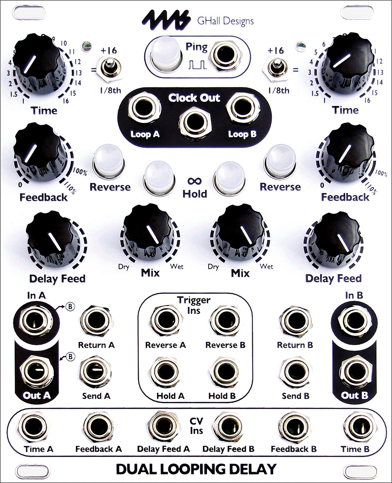
| Dual Looping Delay [DLD] |

Version 5 (not for PCB v1.2-F446) Manual v1.1c
The Dual Looping Delay (DLD), designed by 4ms and Gary Hall, is an advanced audio processor for creative synthesis. Not a tape or analog emulation but a modern crystal-clear digital delay, the DLD combines features of delay, looping, and sample-tight synchronization for powerful and dynamic sound capture and modification. The DLD is designed to integrate seamlessly with modular timebase and sequencing devices such as the 4ms Quad Clock Distributor (QCD), etc.
Select a color:
$415.00
What is a "Looping Delay"?
Modern looping devices grew directly from hardware digital delays of the late 70s and early 80s. A looping delay, modeled on units such as the classic Lexicon PCM42, has the very long storage times associated with dedicated looping, but without triggered record and playback functions.
By default, a looping delay records and plays continuously, though recording can be suspended at any time with Infinite Repeat. Sustain of delays and loops is mainly accomplished with regeneration, allowing an organic, evolving approach to sound creation as new material replaces old, more or less gradually. The 4ms Dual Looping Delay also provides advanced clock input and output facilities that allow for locking delayed and looped material with sequencers and rhythmic devices.
Key Features:
- Two independent delay/loop channels, synchronized to a common time base
- Almost 3 minutes delay/loop time per channel (2:54) in default storage mode (16-bit)
- 48kHz/16-bit sampling rate, option available for 24-bit storage
- Extremely quiet, low noise and low jitter design
- Normalled connections of input and output for flexible use in mono, stereo, or dual mode
- Tap tempo button and clock Ping input set the basis for one "beat"
- Delay/loop time set as a number of musical beats (or fractions of beats) using the Time knob, switch, and CV jack
- Sample-accurate clock output for perfect synchronization
- Loop clock outputs for each channel
- Time switches change range of Time knob from 1/8th notes up to 32 bars
- Digital feedback, up to 110%
- Delay Level control, independent of dry/wet signal mix
- Infinite Hold mode disables recording input and fixes regeneration at exactly 100%
- Reverse mode plays memory contents backwards
- With an infinite loop locked, knobs or CV can "window" around memory, by shifting the loop
- Triggered toggle inputs for Infinite Hold and Reverse
- Send and Return on each channel for feedback with external modules
- CV jacks to control Time, Level, and Feedback
- As new features are developed, firmware can be updated by playing an audio file into the DLD
- 20HP Eurorack module
New features in firmware version 5:
- Ping Lock for each channel
- Quantized Inf/Rev/Time Change Mode
- 24-bit audio (selectable with a jumper)
- Reverse and Inf Hold can be toggled with gates or triggers
- Delay Feed knob can be selected to be audio or linear taper
- Runaway DC at high feedback settings (e.g. resonant delays) is eliminated
- Auto-Muting now has a 1ms attack and decay
- Cross-fade Time (CFT) for splices is now variable (set in System Mode from 0ms to 500ms)
- Selection of External Clock De-jittering algorithms to allow the DLD to sync with many types of external clocks
- Exiting Infinite Hold plays through, without restarting loop
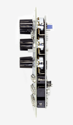
- Module size:
- 20 HP Eurorack format module
- 0.98" (25mm) maximum depth with power cable
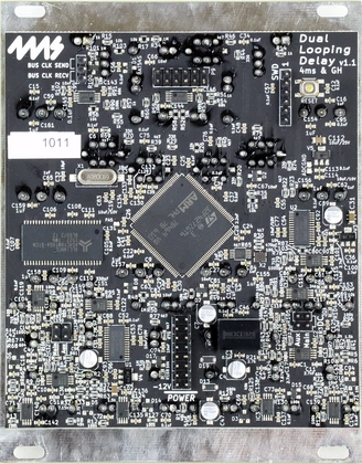
- Power consumption:
- +12V rail: 188mA max (jumper set to 5V)
- -12V rail: 48mA max
- +5V rail: not used
- Connect red stripe of power cable towards the bottom of the module, which is marked with a white stripe and the words -12V and POWER
- Audio Inputs:
- 0Hz (DC) to 24kHz
- 16.8V peak-to-peak maximum before clipping (when AC coupled)
- Optional jumper to choose DC or AC coupling on input.
- Audio Outputs:
- 0Hz (DC) to 24kHz with maximum -1.7dB difference between input and output (see technical specification section)
- +10.5V to -10.5V maximum output
- Soft limiting compression allows for saturation before clipping (can be disabled)
- Clock outputs (Main, Loop A, Loop B):
- 0V to 8.2V
- +/- 2.4us maximum jitter (i.e. 0.001% at 120 BPM)
- Rise or Fall time: <1us
- Pulse Width (Trigger mode) 22ms
- Gate mode 50% (square wave)
- At clock speeds faster than 22Hz, the clock output becomes 50% duty cycle
- 16-to-16 pin power cable
- 4 M3 Knurlie screws